A Retina-like sensor for color images
LTR-Esprit Project - SVAVISCA
October 27, 1997
A Retina-like sensor for color images
|
Visual sensors inspired by biological systems are being studied in many microelectronic centers in the world. One of the groups which originated this kind of research is based in Europe and led by two research centers; the University of Genoa (Genova in Italian!) in Italy and the Interuniversity Microelectronic Research Center (IMEC) in Leuven, Belgium. The main feature exploited by this group is the non-uniform distribution of photoreceptors found in the retinas of most mammals. This feature is a true engineering trick implemented by nature to guarantee the highest possible resolution in one part of the image and simultaneously an almost 180 deg. field of view while constraining the number of "pixels" to acceptable limits. To process the same field of view with the highest possible resolution would require a huge number of neurons (our brain would weigh more than 30 tons!) posing not only mechanical but also power supply problems.
The first implementation of this approach dates back to 1992 and was realized using CCD technology. This project was a collaborative effort including the University of Pennsylvania and produced a device with about 2000 pixels arranged in concentric rings composed of 64 pixels each. The radius of the rings varied in such a way that the central part of the image was sampled with the highest possible resolution. The resolution decreases as the radius of the rings increases and the size of each photosite varies in order to cover the overall area of the sensor (they become bigger towards the periphery).
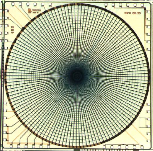
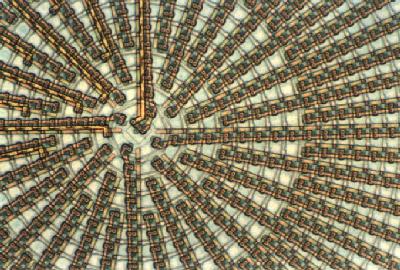
Following this successful implementation, whose main drawback was the complexity of the driving unit, the group at the University of Genoa started a new project with IMEC and other European industrial organizations to realize a new chip, this time using CMOS technology. The application of this EU-funded project (Project IBIDEM - headed by Unitek, a consortium of Italian SMEs) was a videophone for deaf and hard of hearing people. In this case the retina-like arrangement is advantageous because with a relatively small number of pixels it offers both high resolution (required for lip-reading) and a wide field of view (required for observing facial expressions and gestures). Preliminary tests performed to identify the optimal requirements for deaf persons showed that from 6,000 to 8,000 pixels were required with a frame rate of 15 Hz. The CMOS chip is composed of about 8,000 pixels (see fig. 1). Each of the outermost 56 rings of the structure is covered by 128 pixels. In the 20 innermost rings (where the size of the rings does not allow 128 photosites) the number of photosites is halved progressively (see fig 2) down to the very center covered by just one photosite. In the sensor realized using the MIETEC .7 micron CMOS process, the smallest photosites are 14 microns while the large photosites in the periphery are 250 microns wide. The overall size of the chip is 8 mm square and, due to the CMOS technology, each pixel is directly accessible allowing a frame rate of up to 150 frames/sec.
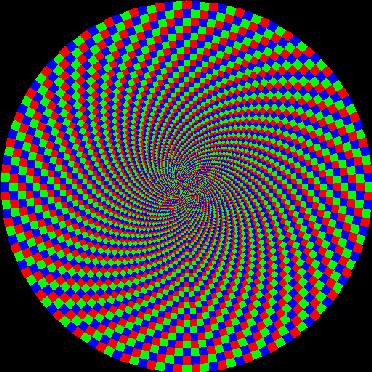
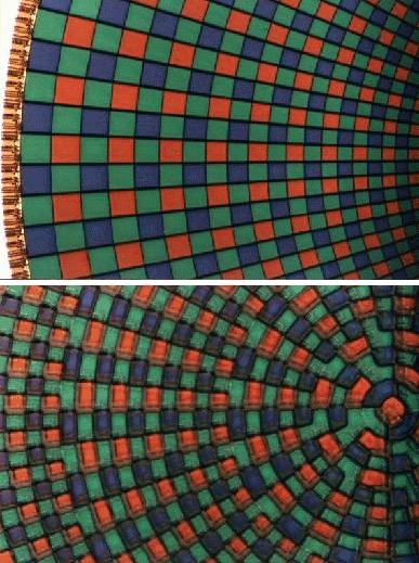
Following this successful implementation (and because the videophone application requires color images), the same CMOS design was used by IMEC to realize (in a new EU-funded project - SVAVISCA - headed by the University of Genoa) a color version of the chip. The sensor is obtained by depositing color filters on the B/W version of the chip. Due to the polar structure of the sensor, specific patterns of Red, Green and Blue pixel placement were tested and two slightly different versions of the color chip realized. The first was called "rotating pattern" (see fig. 3) . In this pattern, each pixel covered with a certain color has the two complementary colors as a neighbor. This applies to both the radial and angular direction of the pixel array. The second pattern (see fig. 4) is a variant of the well known Bayer pattern, where the green pixels dominate. The color reconstruction is symmetrical in the radial and angular direction. Figure 5 shows the result of the color deposition on the wafers. The top figure show the deposition of color filters at the edge of the sensor, and the bottom figure shows the color filters in the fovea. Parts of the readout electronics of the pixels are visible through the filters.
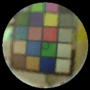
A sample image of the color picture obtained is shown in Fig. 6 . Besides the videophone application, studies on how to use this sensor for robot vision have been going on for many years at the University of Genoa and new interest is arising from the "humanoid" projects where the features of the sensor are particularly promising in allowing robot control without the much higher computational power required by traditional constant-resolution images with comparable resolution and field of view.
Contact: Giulio Sandini (sandini@dist.unige.it)
DIST - University of Genoa - Italy
Fax +39 10 353.2154; Phone: +39 10 353.2779